
EMC Troubleshooting & Hardware Design
An embedded control system undergoing EMC qualification showed behaviours that required deeper investigation. The work focused on understanding how electrical disturbances were coupling through the complete system, including external cabling, chassis bonding, power-input filtering and protective-earth paths.
The investigation led to targeted changes in the grounding and filtering strategy, followed by repeat EMC testing and environmental validation.
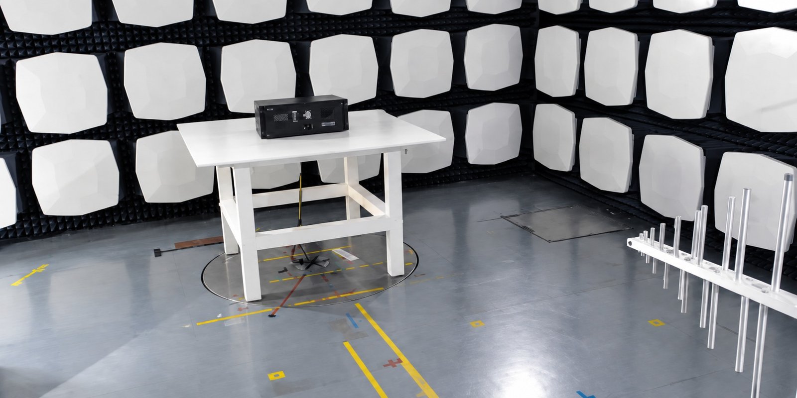
Representative radiated-emissions test setup inside a semi-anechoic chamber
The Challenge
EMC problems are rarely caused by a single component in isolation. In this system, the electronics, enclosure, external wiring and protective-earth connections all formed part of the disturbance-current path.
Initial testing showed that the measured emissions changed significantly depending on the external cable configuration. This indicated that the problem needed to be investigated as a complete system rather than simply as a PCB-level issue.
The objective therefore became to understand where interference currents were flowing, identify the weakest coupling paths and improve the design without compromising normal operation.
Understanding the EMC Behaviour
Radiated Emission measurements were repeated with different system configurations so that the influence of the external wiring and enclosure connection could be separated.
With serial and Ethernet cabling connected, the high-frequency emission level increased substantially. Removing these connections improved the result, indicating that the cables were participating in the RF current path.
Attention then turned to the mechanical connection between the front panel and protective earth. Improving this connection reduced the measured impedance from approximately 20 Ω to below 1 Ω and produced a corresponding improvement in radiated-emission behaviour.
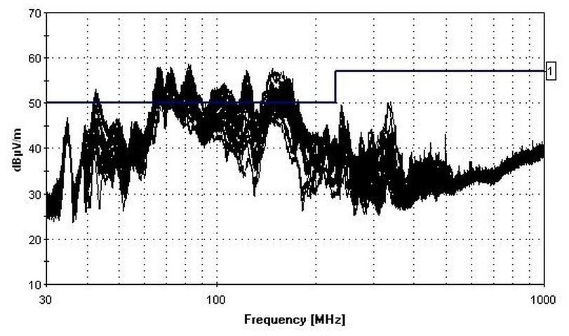
Representative radiated-emission measurement used to investigate the influence of system configuration and external cabling.
(Antenna in horizontal polarisation)
Improving the Chassis Bond
The investigation highlighted the importance of a low-impedance connection between the enclosure sections and protective earth.
A painted mechanical interface was preventing an effective electrical bond between parts of the chassis. The contact area was therefore modified to create a direct metal-to-metal connection, providing a substantially lower-impedance return path for high-frequency disturbance currents.
This was a relatively simple mechanical change, but it had an important effect on the EMC behaviour of the complete system.
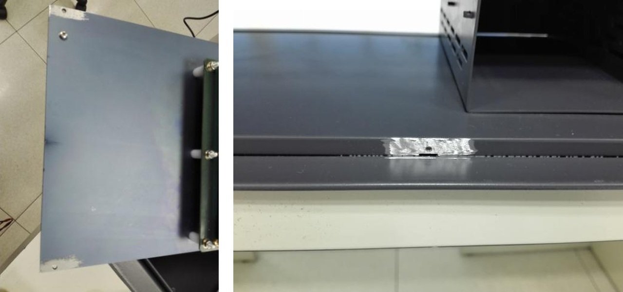
Chassis contact areas modified to improve metal-to-metal bonding and reduce the impedance of the protective-earth path
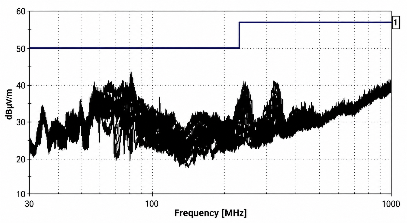
Radiated-emission measurement after improving the chassis bond
Surge Immunity Investigation
The grounding investigation was complemented by surge-immunity testing of the power interface.
During one test configuration, removing the normal line-to-earth protection exposed a more fundamental weakness: high-energy surge disturbances were able to couple into the control circuitry and cause the front-panel software to lock.
Rather than treating this simply as a software failure, the behaviour was investigated as an EMC current-path problem. The disturbance needed a controlled route away from the sensitive digital electronics.
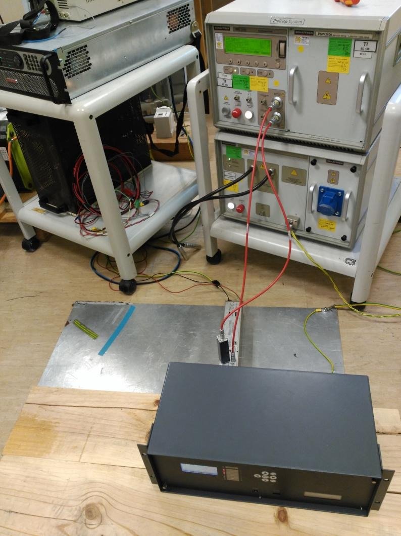
Representative conducted-immunity testing used to investigate coupling through the power-input and protective-earth paths
Power-Input Filter Redesign
Surge testing showed that high-energy disturbances coupled between the supply lines and protective earth could reach the control circuitry and cause the embedded software to lock.
The power-input EMI filter was therefore redesigned to provide a lower-impedance path for common-mode transient current before it could couple into the sensitive electronics.
A 4.7 nF Class Y1 capacitor was added from each supply line to protective earth, while the existing 2.7 nF Class Y2 capacitors were replaced with 2.2 nF Class Y1 devices. At the same time, the front-panel earth connection was reinforced to improve the return path for surge current.
The objective was not simply to add more filtering, but to control where the transient current flowed: directing it towards the chassis and protective-earth structure rather than allowing it to propagate through the control electronics.
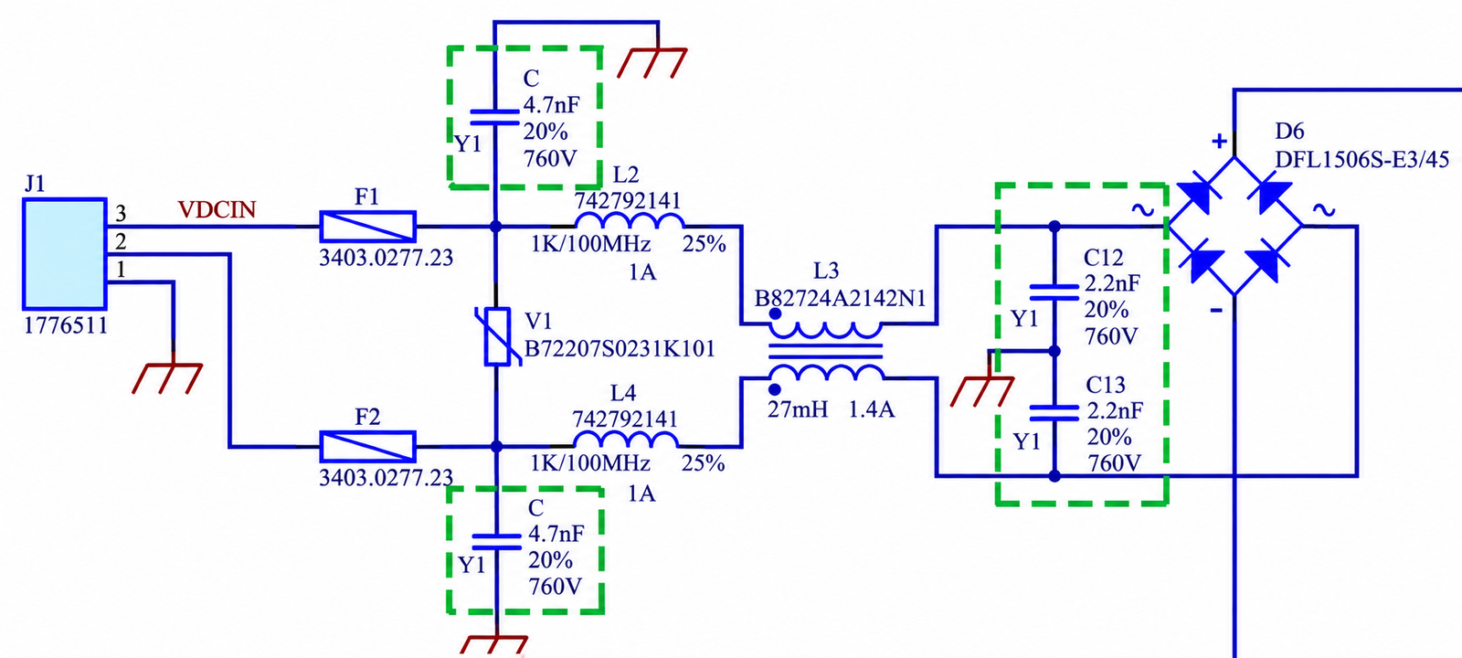
Revised power-input filtering, including the updated Class Y capacitive paths to protective earth
Key hardware changes
– Added 4.7 nF Class Y1 capacitance from each supply line to PE
– Replaced 2.7 nF Class Y2 capacitors with 2.2 nF Class Y1
– Reinforced the front-panel/chassis earth connection
– Provided a more controlled common-mode surge-current return path
Verification Across Multiple EMC Tests
The revised system was not evaluated using a single pass/fail test. Verification covered a range of electromagnetic disturbances representative of the intended environment.
Radiated RF immunity, electrostatic discharge, fast electrical transients, conducted RF disturbances, surge events and supply-voltage interruptions were all used to exercise different coupling mechanisms.
During radiated RF testing, the system remained operational while exposed to a 10 V/m field.
Electrostatic-discharge testing included both contact and air discharges, while fast-transient testing was performed above the basic specified level to provide additional margin.
Behaviour During Supply Interruptions
Power interruptions and voltage dips were also tested to understand how the system behaved during temporary loss of supply.
Short interruptions were tolerated without loss of normal operation. During the longest complete interruption tested, communication with the PC was temporarily lost, while the embedded software continued operating and the communication recovered automatically afterwards.
This distinction was important: temporary loss of an external interface was treated differently from a failure of the embedded control function itself.
Environmental Validation
EMC robustness was only one part of the validation programme. The hardware was also exercised under demanding temperature conditions to understand how the complete system behaved outside normal laboratory ambient conditions.
Cold and dry-heat testing included extended exposures down to −40 °C and up to +85 °C. The main electronics continued to execute their test functions at these extremes, although the display itself showed reduced readability outside its normal operating temperature range.
Importantly, the display recovered when the system returned to its normal operating-temperature region.
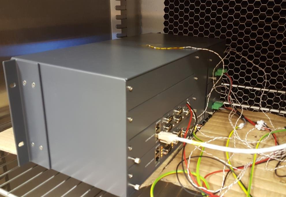
Complete system instrumented for environmental testing and temperature monitoring
Outcome
The investigation identified how external cabling, chassis bonding and power-entry filtering were influencing the EMC behaviour of the system.
Improving the chassis connection provided a lower-impedance return path for high-frequency disturbance currents, while revisions to the input filtering reduced the susceptibility of the control electronics to surge events.
More importantly, the work turned individual EMC symptoms into an understanding of the underlying coupling paths. The revised hardware could then be evaluated systematically across emission, immunity, supply-interruption and environmental tests rather than relying on isolated fixes.
Need support with EMC or hardware robustness?
ElectronPath supports EMC troubleshooting, grounding and filtering improvements, electronics design review, power-integrity investigation and hardware verification for existing products and new developments.
Discuss Your Project →